My first cone project was for my upscale Estes Cherokee D in early 2010. After failing at the hot-wire method, I attempted a wood frame filled with expanding foam. Better than the hot-wire but still unacceptable, very labor intensive, and somewhat expensive with the foam required. Time was a factor and I really needed to get a cone built. Once I found Bob's method it looked simple enough so I gave it a try. I was quite pleased with the experience and I had a very nice nosecone as a result.
Below are some photos of the "failed" wood-frame method for creating the first Cherokee-N cone. I provide them so you can see some alternate construction techniques...maybe you can capitalize on them.
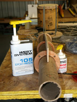
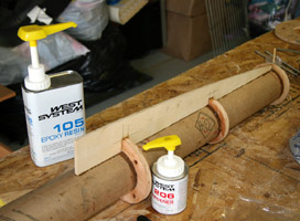

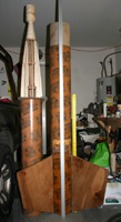
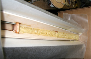
- The Cherokee-N core tube with one profile plate installed.
- The Cherokee-N core tube with one profile plate installed.
- A view of the Cherokee-N core tube with some profile plates installed - I used eight total.
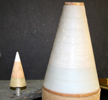
- A Cherokee-N components family portrait.
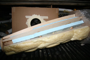
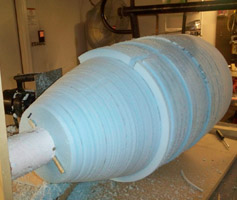
- Original plan was to occupy volume with blue foam to minimize two-part liquid foam use.
- Some two-part liquid foam already in place with more to go.
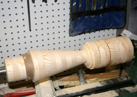
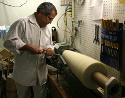
- Brad trimming the spinning cone on the wood lathe.
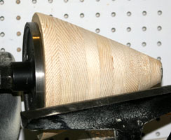
In the end, this cone was a bit out of round and it looked pretty helpless getting it where we wanted it to be. I decided to shelve this cone once I discovered Bob Heningers method.
The Nose Cone Rotisserie
Introduction
I constructed the work surface from 1-inch thick particle board shelving material. I already had it on hand in the garage, and I originally bought the stuff at Lowe's for about $1.50. My original uprights were simple pine boards (again, I used what I had on hand) to support the horizontal 1/2-inch all-thread rod. I upgraded those uprights in February 2011 to 1-inch square steel tube. This is the square tube with all the holes in it on one-inch centers. L-brackets are used to mount the uprights to the work surface. After drilling the holes for the L-brackets, I embedded 5/16-18 tee-nuts in the bottom of the work surface to accept the hex-head bolts that secure the L-brackets and uprights. There are various ways to mount the uprights and in fact I may revise my mounting scheme in the future. When I revised the uprights I also switched to a 1/2-inch diameter cold-rolled rod that I had on hand.
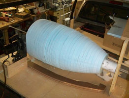
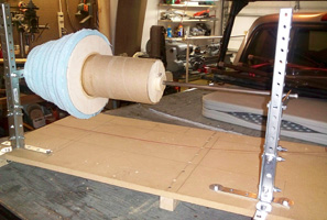
- The jig with the original wooden uprights. Dwain's Big O cone. This was also before I added the braces to the router jig, so you can see where the flex in the router jig allowed the cutting bit to wander into the material. I've since added braces to the router jig and this all but eliminates this condition.
- Recently redesigned jig with steel uprights - Feb 2011. This is a transition for my Saturn 1 Block 1 SA-4.
I had to expand the holes in the square tubing to accept the 1/2-inch (13mm) diameter steel rod I use as a spit. My original spit was 1/2-13 all-thread rod, but I've since switched to the smooth cold-rolled steel rod. My holes are 9.5-inches above the work surface, giving me an 19-inch capacity. Any of the holes will work as long as they are the same height above the work surface: the higher up they are, the larger the diameter of cones you can turn.
My work surface is approximately 40-inches wide by 20-inches deep. With the uprights mounted at the extreme corners I have about a 36-inch length capacity. There is enough room in "front" of the spit to safely handle the router jig I assembled. The largest cone I've made so far is 16-inches in diameter for Dwain Desbian's "Big O" project we flew in October 2010.
Building the Nose Cone
Step-by-Step
It is beyond the scope of this article to discuss nose cone design and theory. What follows is a method I have learned to fabricate nose cones suitable for high-power rocketry. These methods can also be applied on a smaller scale to create custom nose cones for low- and mid-power model rockets.
Step 1: Select the nose cone design
Whichever cone you design it will have a specific profile you want to try and duplicate. Whether you are designing your own cone or replicating a cone from an existing design, it will have a specific profile. One way to create your profile is to make a photocopy of a drawing or photograph and enlarge it to the required size. This may be done any number of ways including a commercial copy center, computer design software, or a simple copying machine. Once you have your profile you need to make a profile pattern for the router to follow.
I also like to create a full size "schematic" of my cone so I can see how many foam circles I'll need, the diameters of the pieces at the various "stations", where my foam will end and my wooden tip will begin, etc.
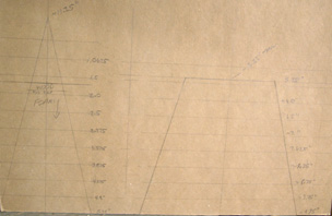
- A typical cone schematic. It's a full size drawing; the horizontal lines are one-inch apart (thickness of foam) and numbers on the right is the diameter of each piece at that station. If you are going to cut circles to closely match the diameters, be sure to allow for the taper and cut the circles slightly oversize.
Step 2: Create the profile pattern
If your cone has a curved profile, one way to make the profile pattern is from masonite. This material is usually dark brown in color and typically comes in 1/8" and 3/16" thick sheets. You can usually buy a 4ft x 8ft sheet at a home improvement center for less than $10 and you can make a lot of profiles from one sheet. Alternately, if your cone is a simple straight taper, you can use any straight-edged piece of hard material.
Transfer you pattern to the masonite or other material and cut it out with a jigsaw or similar. A belt sander is handy to smooth the profile to the final shape. You need a very smooth edge surface for the router to follow so take care to make it as smooth as possible.
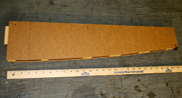
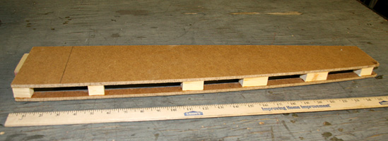
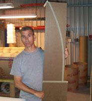
- Cherokee-N profile pattern.
- Another view of the pattern.
- Big O profile pattern before cutting it out.
Step 3: Profit. Yes, it's a South Park reference :)
Step 4: Cut the foam discs
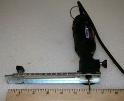
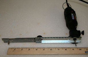
There are various methods you can use to cut the foam circles. I like using my Dremel tool with the circle cutter attachment. The circle cutter can create cirlces up to about 12" in diameter. When I made the cone for Dwain's Big O rocket, I had to fabricate an extension to create the rings for the 16" diameter cone. You can also use a coping saw or other saw suitable for foam. Be prepared to make a mess while cutting the foam.
Foam suitable for cones is that typically used in the construction industry as insulation. It comes in 2ft x 8ft sizes and is usually blue or pink depending on the region. It is also available in 1"and 2" thicknesses. A sheet usually costs well less than $10. Depending on the diameter and length of your cone you may need more than one sheet per cone.
Set the circle cutter to a diameter about an inch larger than your desired diameter and start cutting circles. If you drew a profile on paper, you may have drawn parallel lines across the paper denoting the thickness of your foam circles. You can treat these lines as stations and calculate the diameter at various stations and cut appropriately-sized foam circles. This will help save material, reduce the amount of foam dust, and lower the cost of your cone. Alternately, you can cut all the circles the same size and just deal with the mess. Cut as many circles as you need to cover the length of the foam portion of the cone.
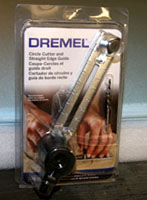
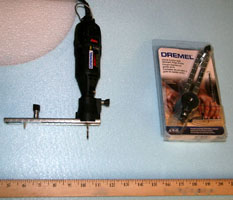
- Dremel Circle Cutter attachment.
- Circle Cutter attached to a typical Dremel.
- Shows the 12-inch capacity of the stock circle cutter.
- Home-made extension to cut larger circles.
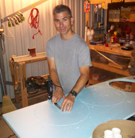
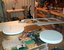
- Starting to cut circles for the 16-inch diameter Big O cone. This necessitated using the home-made extension seen above.
- Circles for the 16-inch diameter Big O cone.
At some point before you begin laying up the cone you should decide what size central core tube to use. Any suitable size of thick-walled tube will work here. I used a 3-inch diameter USPS mailing tube for the Cherokee-N and Big O projects. I ve also used 2-inch diameter and smaller tubes. I m always on the lookout for cardboard tubes, especially those designed for mailing stuff. UPS and FedEx also have suitable mailing tubes. The tube may come in handy if you need to add nose weight for center-of-gravity purposes.
The next step is to cut plywood circle plates for the top and bottom of the foam. Depending on the size of the rocket, I use either or 3/8 birch plywood. However, for the Big O rocket I used birch plywood. A fresh bit in the Dremel will help you create nice clean circles. Cut each plate to match the upper and lower diameter of the foam circles. At this time you might as well figure the diameter for the plates for the nose cone shoulder. At lease do one for the top of the shoulder so you can center the shoulder on the nose cone. if you plan on using a plate at the bottom of the shoulder, your central core tube should extend down through the shoulder so you can keep everything lined up. It s not a bad idea to create a wood plate for inside the shoulder at the bottom.
The diameter of your core tube will determine the diameter of the hole to cut in the center of each foam circle and wood plates. If you have a wood lathe, it will also determine the diameter and length (above the foam) of your non-foam tip. I like to use the Dremel circle cutter to cut the center holes too. It creates really clean holes and minimizes foam dust. Cut the foam center circles for a relatively tight fit on the core tube, but a little play is acceptable. The center holes in all the plywood plates should provide for a tight fit on the core tube.
Step 5: Laying up the cone
I normally begin the lay-up process by gluing the top plate flush to one end of the core tube. Use wood glue or epoxy to secure the plate. Ensure the plate is flush and perpendicular to the core tube, and let the tube stand upright with the plate flat on the ground and the tube standing straight up. Having the plate secured in place provides a secure foundation on which to stack the rest of the foam. Alternately, you can start with the bigger plate at the bottom. If your core tube extends into where the shoulder will go, ensure you have enough tube length to cover the required length (i.e. to the bottom of the shoulder coupler.)
I like to use West System two-part epoxy to secure the foam to the core tube and to each other on the facing surfaces. Mix up some West System and apply a light layer to the wood plate. Make sure the mating surfaces are free of foam bits or other debris and slide the first foam circle in place. Continue with the epoxy and foam circles until you ve used them all. Bob says in his article to keep the epoxy away from the edge of the foam. I haven t had any problem when the router bit hits the epoxy but it is audible. And I have felt bits of cured epoxy hit me so be sure to always use eye/face protection when using power tools. You don t need epoxy all the way to the edge; use just enough to glue the pieces together. If I m going to be sloppy with the epoxy it ll be at the tube / circle joints.
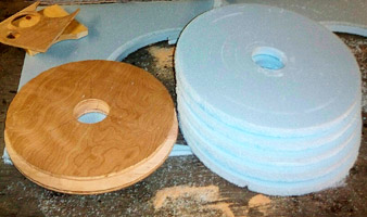
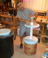
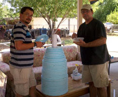
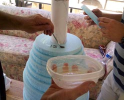
- Some of the plywood / foam rings for the Big O project.
- Rick stacking foam rings on the completed coupler / core tube assembly.
- Dwain and I assembling the cone one ring at a time with epoxy between all rings. For this cone we did not immediately epoxy the rings to the tube.
- Applying West System epoxy to the stack. I wanted to be able to remove the cured stack from the tube so I could form the cone on the jig.
After all the foam is stacked on, epoxy the other wood plate in place, making sure it is perpendicular to the core tube. It s a good idea to place a weight or otherwise clamp the stack to ensure the epoxy cures with the foam compressed together. If you have used consecutively smaller foam circles, it may be difficult to keep it upright with a weight on top. Because of this, I usually just make the rings all the same size. Sure, I have more waste to clean up and wasted foam but it s just the way I prefer to do it. I usually use plywood scraps of the same thickness under the exposed foam (next to the end plate touching he ground) for more support while I have the stack weighted down.
Step 6: Prepare the cone for turning
Two wood plugs need fabricated to temporarily fit in the ends of the core tube. The plugs should be a very tight fit, but not so tight as to distort the tube. I use my Dremel circle cutter and pine to make the plugs. After they are cut, a hole needs drilled in the center as close to the exact center as possible. The metal spit rod will fit through these holes and the cone will spin on this rod when you create the shape of the cone, so it is important the holes are centered to minimize wobble.
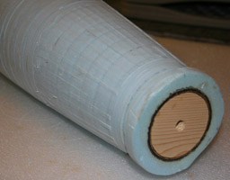
- One of the original rejected Cherokee-N cones with the wood plug temporarily installed in the forward end.
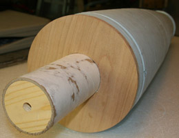
- One of the original rejected Cherokee-N cones with the wood plug temporarily installed in the aft end.
Step 7: Mount the profile pattern
The profile piece created earlier now must be properly positioned for the router to do the job correctly. The smooth, profiled edge faces away from the spit and measuring the exact location is critical. With a masonite pattern I normally mount several wooden standoffs to the work surface at approximately where the pattern will go. I then mount the profile pattern to the standoffs. I use coarse drywall screws to make both attachments.
Step 8: Mount the cone on the spit
Slide the metal rod through one of the metal uprights, then install one of the stop nuts. Feed the rod through both wooden plugs in the cone and then install another stop nut. Continue to feed the rod through the other metal upright until an inch of rod protrudes past the metal upright. Install a stop nut on this end of the rod and tighten it down. Move the cone to the left as far as possible then tighten the stop nuts on either side of the cone. Finally, install a stop nut on the rod end opposite the first stop nut. These nuts should keep the cone from sliding left to right on the rod but still allow the cone to spin about the rod.
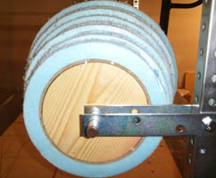
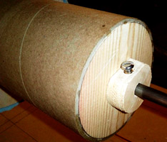
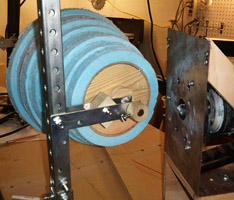
- Forward end of the Saturn 1, Block 1 SA-4 transition mounted on the spit.
- Aft end of the Saturn 1, Block 1 SA-4 transition mounted on the spit. Homemade wooden "drill stop" installed to minimize horizontal travel.
- Forward end of the Saturn 1, Block 1 SA-4 transition after adding home-made wooden "drill stops" to minimize horizontal travel.
Step 9: Prepare to make a mess
Depending on your router setup and how much larger than the finished diameter your circles are, you may have to make at least one complete pass over the cone before your router base will even touch the pattern. During this initial trimming, I often place a spacer between the pattern and the router base to keep the router bit from removing too much material by mistake.
There are two basic methods to remove the foam. One is to position the router and slowly rotate the cone, taking material away from the circumference one bit width at a time. The other way is to move the router from one side to the next without spinning the cone. Either way works but I usually use the rotate method. I ve made cones with and without the wood plates on each end of the foam. In either case, I start the router outside of the material and slowly move the router until the spinning bit makes minimal contact with the material especially if there is wood. Then I slowly rotate the cone through one revolution. Note: occasionally, the router bit may grab the wood or foam and start the cone spinning rapidly on its own. If this happens, just try to back the router away from the cone and stop the motion and proceed.
Move the router a small distance and repeat the process until the wood disc has been trimmed. Then proceed with the foam, again moving the router about one bit width at a time after each revolution of the cone. If wood is on both ends, carefully trim the other wood disc. A small amount of wood splintering can be expected on the outside if you move too fast or rotate the cone. After initial trimming it s a good idea to clean up the area with the shop vac or dust pan and broom. There will be a LOT of foam bits all over the place, including between the router base and the pattern.
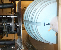
- First horizontal cut on Dwain's Big-O. Note the profile pattern below the nose cone.
- After removing considerable material. This is such a big cone I used both side-to-side and rotating motions to remove the foam.
After the initial trimming I usually re-measure the diameter(s) as a progress check and to ensure they will be correct when the final cutting is done. You may have to adjust the pattern or change the depth of the router bit to get it right. Once you are sure your diameters will be correct, it s time to make the final cuts. Repeat the process described above until foam has been removed to the final, desired shape. Then clean up the mess, and stand back and admire your handy work.
If you are satisfied with the result, remove the cone from the spit and remove the end plugs from the core tube. Depending on your construction methods you will have to add a shoulder to fit into the body tube and a nose tip to complete the cone.
Making the shoulder
Nearly all nose cones need a shoulder to position the cone in the adjoining body tube. Various factors like the diameter or your rocket and expected motor thrust will help determine the best method for creating and mounting your shoulder. A larger rocket using powerful motors should imply a stronger nose cone shoulder. For the most strength I usually create a double-walled shoulder with end plates at both ends and a core tube that extends all the way through the entire length of the shoulder. A larger rocket with relatively heavy motors may require nose weight anyway, so incorporating some of that weight into the nose cone building process is one way to accomplish it. The end plates help center the shoulder on the cone, and you can use either the rear end plate or the core tube as a recovery harness mounting point. The choice is up to you, but choose the method that best works for your application.
Creating a shoulder is relatively easy. A lot of commercially available airframe tubes have associated couplers that will work well. If the tube is non-standard (like Sonotube) I usually just use a piece the same diameter as the airframe tube about one airframe diameter (caliber) in length. I slice it lengthwise and insert it into the airframe. The tube will overlap itself, so mark the overlap, remove the shoulder and extend the overlap mark the length of the coupler. Carefully cut away the overlap and reinsert the shoulder into the airframe tube. The shoulder should be a nice smooth fit into the airframe and the cut edges should match up. If you are satisfied with the fit, you have a choice to make. One option is you can take the strip you cut away (or make an even wider strip) and epoxy it over the joint. Or, you can repeat the process and make another shoulder to fit inside the first one and double it up. I like the second option as it makes a nice strong shoulder, and I can cut the second piece a little shorter so it creates a lip inside the shoulder that my end-plate(s) can butt up against.
Whichever method you choose, the best way to create the shoulder is to tape some wax paper over the outside of the shoulder making sure to cover the joint. Use enough wax paper to extend far enough past the edge so you won t accidentally epoxy the shoulder inside the airframe tube. Insert the shoulder into the airframe while making sure the wax paper stays in place. Glue or epoxy the strip (or the shoulder doubler) over the joint and let the epoxy fully cure. Once cured, remove the shoulder.
The method you used to make your shoulder will determine how you mount it to your cone. If you have just a shoulder held together with the single strip, you can simply flush mount the edge of the shoulder to the base of the nose cone. I nice fillet of epoxy around the inside of the joint will probably hold up well for a flight or two, but we can do better with the end plates and longer core tube.
You need to think about the recovery harness attachment point. You can add a u-bolt or two (or any other appropriate hardware) to the bottom end plate before gluing the plates in place in the shoulder. You could also choose to plug the core tube and secure the attachment hardware to it.
If you have end plates and an extended core tube, I would first mount the end plates in the coupler and let them cure up. Then apply some wood glue or epoxy to the adjoining wood surfaces of the coupler and nose cone base plate, and slide the shoulder onto the core tube until it is flush against the nose cone. You may need to rotate the shoulder to find the best alignment and center the shoulder on the nose cone. If you haven t already cut the core tube to final length, cut it so a sufficient amount extends past the end plate typically a half inch or so. Just leave enough exposed to apply a fillet of glue/epoxy on the core tube / end plate joint. .
